11/22/2019

Introducing MPO/MTP Fiber Patch Cord,Optical Fiber Connector

With the increasing demand for high-speed, high-capacity optical communication systems, MTP/MPO fiber optic connectors and fiber optic patch cord are ideal solutions for high-density cabling in data centers due to their cores, small size, and high transmission rate.
The MPO fiber patch cord is a combination of an MPO connector and a fiber optic cable. The MPO connector type is distinguished by several factors according to IEC 61754-7: Array Number, Male-Female, Polarity, Polishing type (PC or APC).
MPO fiber optic connector types
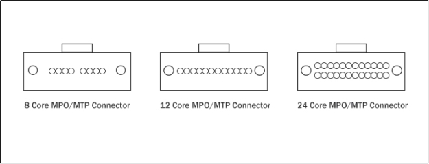
Currently, the factory termination assembly of the MPO connector can accommodate 6 to 144 fibers, among which 12 and 24-core MPO connectors are the most common types. According to IEC-61754-7 and EIA/TIA-604-5 (FOCIS 5) specifications, 12-core fibers are usually arranged in a row, which can consist of one or more columns of fibers in the same MPO connector. There are 12-core fibers MPO connectors and 24-core fibers MPO connector. 40G MPO-MPO fiber jumper generally adopts 12-core MPO multi-mode ferrule; 100G MPO-MPO fiber jumper, generally uses 24-core MPO ferrule. There are also 16 single-row fiber array types on the market that can be divided into multiple columns to form 32 cores or more. The 16/32-core MPO fiber optic connector will be the best solution for low-latency, the ultra-high-speed transmission of next-generation 400G networks.
84
Male and Female Connectors
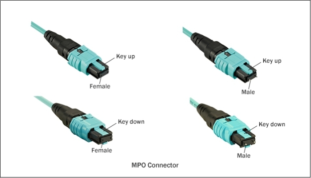
MPO connectors contain several parts such as boot, coupling/housing assembly, ferrule, guide pins, and so on. Because of difference pins types, the MPO connector can be either male or female. The male connector has metal guide pins to ensure fiber alignment when mating while the female connector has no pins. These pins make sure that the connector fronts are precisely aligned on contact and that the fibers’ end-faces aren’t offset.
85
What is MTP?
MTP is “Multi-fiber Termination Push-on”, which was developed by US Conec and improved attenuation and reflection on the standard MPO connector with higher overall performance. Externally, there is little discernible difference between the MPO and MTP connectors. They are completely compatible.
MPO/MTP fiber connectors and fiber patch cords provide a simple and easy-to-manage fiber-optic cabling solution for FTTH and data centers that require high-density integrated fiber-optic system. It is likely to be a hot-demand product for future 5G data center construction.
87
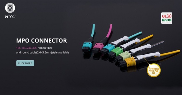
HYC has 19 years of experience in research and development of passive basic components for optical communications, supplying MPO/MTP fiber connectors and fiber patch cords of various specifications.

11/18/2019

What are the features of LC Uniboot compared to traditional LC fiber connectors?

The traditional LC duplex fiber optic connector is generally composed of two LC simplex connector through a clip, with a single fiber inside each connector. The LC Uniboot connector is a modified LC duplex connector. The two fibers are simultaneously placed in a 2.4mm or 3.0mm jacket to achieve a single-tube dual-core function, which significantly reduces cabling space requirements. So what is the difference between an LC uniboot connector and a traditional LC fiber connector?
Compact design for high-density applications
LC Uniboot optical connector adopts single-tube dual-core, half-surround tab end to reduce the number of fibers. Compared to traditional LC duplex jumpers, the uniboot connector effectively reduces installation volume by 50%, including improved cable management, airflow, and cabling.
700_400_38
Easy polarity revisable
What is fiber polarity? The polarity of optical fiber is the direction of optical signal propagation in the optical fiber. Normally, there are a transmitting signal terminal (Tx) and a receiving signal terminal (Rx). The Uniboot connector is an innovative design that allows the fiber polarity to be switched without the need for special tools.
700_400_39
A push-pull tab design
HYC’s LC Uniboot connector is an exclusive patent design with a push-pull tab, which ensures easier release from the high-density environment. The fiber optic connector with a push-pull tab is easy to insert or remove even in high-density environments. A half-surround tab end avoids the cable ganged each other.
700_400_40
The innovative LC uniboot optical fiber connector, with its unique structure and compact design, performs better than conventional LC duplex connectors in a high-density cabling environment, making it an ideal choice for data centers and FTTx.

11/14/2019

The Features of Slide Out Drawer Optical Fiber Distribution Box

As the number of users increases, optical fiber cabling becomes more and more complicated. Optical Fiber Distribution Box (ODB) is an important equipment in the optical transmission system. It is usually placed in an optical communication room or rack to manage fiber terminals and implement cabling functions. It is widely used in optic communication room, fiber optic connecting devices to manage fiber terminals and it can function as the protector of optical cable termination and line transmission.
In general, there are three types of fiber optic distribution boxes: rack mount type ODF, cabinet mount type ODF, and wall mount type ODF. Rackmounts are usually 19 inches and come in units of 1U, 2U, 3U, or 4U. U is Unit, which generally refers to the height of the panel device. To be precise, 1U is equal to a rack height of 44.45 mm (1.75 inches) and a 2U mounting height is 2 x 44.45 = 88.88, which is 3.5 inches high. The height of the 3U is 3 x 44.45 = 133.35mm, which is 5.25 inches. The standard was established by the Electronic Industries Association (EIA). The main difference between the IU/2U/4U fiber distribution box is the height and the number of fiber cores that can be supported.
700_400_30
Rack mount enclosures are the most commonly used fiber-optic enclosures for the telecommunications industry. They come in different sizes and types with customizable panels and trays. Rackmount fiber optic enclosures are divided into different installation methods: drawer type, swing-out type and cover removable type. Drawer and swing-out types of fiber enclosures are more convenient to use but they are also more expensive. The cover removable type fiber enclosure is cheaper, but not as convenient. The cover removable type rack mount enclosures are the most commonly used fiber-optic enclosures for the telecommunications industry. What are the characteristics of the drawer type fiber enclosure?
700_400_31
Split tray design, easy to operate
The drawer-type fiber enclosure uses a split tray, and the module box can be pushed and pulled independently when they are stacked and installed. The mounting area is equipped with a separate pull button lock to prevent slipping. The tray has a sliding and locking function, which can be directly pulled out like a drawer when in use, and can be wired after being locked out, which is very convenient.
700_400_32
Compact structure, super density cabling, effective space-saving
The compact design allows for high fiber density and more port number to increase cabling density and maximize cabinet space savings. This HYC’s high-density unique design patch panel, with maximum LC connecting & cabling, adopt the high-strength environmental lightweight material and superior surface treatment technique, which make the panel achieved complete function and various flexible cabling solution. Each cassette module is designed with 24 fibers, 6pcs cassettes can be put in 1U, which equipped up to 144 core LC interface or 72 core SC interface. 2U can accommodate 12 cassettes, with 288 core LC interface or 144 core SC interface; 4U can be equipped with up to 576 core LC interface or 288 core SC interface.
700_400_33
Flexible design, efficient cable management
There is an independent cable management frame at the back of the enclosure, which can easily manage the cable and ensure the air circulation in the space. HYC’s fiber optic panel is designed with good cabling management. The independent cassette at the front side is for smart cable management. Multi-layer cassette for easy separated operation. The independent cable management frame at the backside is to fix the trunk cable. The redundant trunk cable ensures the cassette move properly.
700_400_34
The drawer-type fiber distribution box is flexible in configuration, easy to install, easy to maintain and manage. It is widely used in patch cord connection, fiber fusion, fiber storage, and high-density MTP cabling management.
HYC can design a fiber-optic enclosure that meets all your business needs. HYC Patch Panel Enclosures are available in 1U, 2U, and 4U heights and may be configured to offer dozens of high-performance networking solutions.
HYC Co., Ltd(HYC)is a national Hi-tech optoelectronics company engaged in R&D, manufacture, and marketing of fiber optical products. Providing professional products and services for fiber connectivity, WDM, PLC splitter, and high-density datacom cabling. HYC products and solutions widely applied in 4G/5G, Data Center and Cloud Computing industry, etc.

11/04/2019

A comprehensive understanding of fiber optic connectors

Optical fiber connectors are used most often to transmit light by connecting two optical fibers instead of splicing. It is a flexible device that widely used in fiber-optic communications systems. Optical fiber connectors ensure precisely connections between the two ends of the fibers so that the optical energy output from the transmitting fiber can be coupled to the receiving fiber to the maximum extent. Better connectors will have little impact on the system due to its involvement. Since the outer diameter of the optical fiber is the only 125um, and the light passing core is smaller. The cores of single-mode fiber are only 9um, and the multi-mode optical fiber has 50um and 62.5um. So it is important to ensure the properly aligned.
Main component: Ferrule
One of the most important main components of fiber optic connector is ferrule. The quality of the ferrule directly affects the precision connections of the two fibers. Ferrule is usually made of different materials such as ceramic, metal or plastic. Most of the ferrules used in optical connectors are made of ceramic material (zirconia) due to its hardened characteristics, such as good thermal stability, high hardness, high melting point, wear-resistance, and high processing precision. The inner diameter of the ceramic sleeve is slightly smaller than the outer diameter of the ferrule, and the slitted sleeve tightens the two ferrules for precise alignment.
700_400_21
In order to make the end faces of the two fibers better contact, the ends of the ferrules are usually poshing into different structures. PC, UPC, and APC are the polish styles of ferrules inside the fiber optic connectors. PC is Physical Contact. The two end faces are polished to be slightly curved or microspherical, and the fiber core is at the highest point of the bending. This eliminates the air gap and forces the fibers into physical contact. APC is Angled Physical Contact. The end face of APC is usually ground into an 8-degree angle. The 8° angled bevel makes the fiber end face tighter and reflects light through its beveled angle to the cladding instead of returning directly to the source, providing better connection performance. UPC (Ultra Physical Contact) is based on the PC to optimize the end face polishing and surface finish, the end face looks more dome-shaped. Connector connections need to be in the same end face structure, for example, APC and UPC cannot be combined, resulting in poor connector performance.
700_400_23
Basic parameters: insertion loss, return loss
Due to the different ferrule end faces, the performance of the connector loss is also different. The optical performance of fiber optic connectors is primarily measured by two basic parameters: insertion loss and return loss. So what is the insertion loss? Insertion Loss (“IL”) is the loss of optical power caused by the connection. It is mainly used to measure the optical loss between two fixed points in optical fiber, which is usually caused by the transverse deviation between two optical fibers, the longitudinal gap in optical fiber joints, the end mass, etc. The unit is expressed in decibels (dB). Lower the insertion loss, better the performance. The general requirement should be no more than 0.5dB.
Return Loss (“RL”) refers to the parameter of signal reflection performance. It describes the power loss of optical signal return/reflection. The value is usually expressed in decibels (dB). The larger, the better. The typical RL value of APC connector is about -60db, and that of PC connector is about -30db.
Except for the two optical performance parameters of insertion loss and return loss, there are also other parameters should be considered including the interchangeability, repeatability, tensile strength and operating temperature of the fiber optic connector.
Fiber optic connector types
There are various fiber connector types in the market, such as LC, SC, FC, ST, MU, MT, MPO/MTP and so on.
700_400_22
LC connector
The LC optical connector is made with an easy-to-use modular jack (RJ) latch mechanism. The size of the pins and sleeves used in the LC connector is 1.25 mm, which is the half-size of SC, FC, etc..
SC connector
SC fiber optic connector (‘Subscriber Connector’ or ‘Standard Connector’) is a snap-on standard square connector, which features a push-pull coupling mechanism, and does not need to be rotated. This type of connector is usually made of engineering plastics, which are inexpensive and easy to insert and remove.
FC connector
FC fiber connector (Ferrule Connector) and the SC connector are the same sizes, except that the FC is made of a metal sleeve and the fastening method is a turnbuckle. It has the advantages of simple structure, convenient operation, easy manufacture, and durability, and can be used in a high vibration environment.
ST connector
The ST fiber optic connector (Straight Tip) has a rounded outer that made by a 2.5mm ring-shaped plastic or metal. The bayonet-style keyed coupling mechanism, which is commonly used in fiber distribution frames.
MTP/MPO connector
The MTP/MPO fiber optic connector is a special type of multi-fiber connector. The structure of the MPO connector is complex, connecting 12 or 24 fibers in a rectangular fiber ferrule.
In addition to the above, the connector types include MU connectors, MT connectors, MTRJ connectors, E2000 connectors, etc. Due to low cost-benefit, SC connector is probably the most commonly used fiber optic connector. LC fiber optic connectors are also a commonly used fiber optic connector, especially for connection to SFP and SFP+ fiber optic transceivers. FC connector is mostly used in single-mode and is relatively rare in multimode fiber. Complex designs and metal housing makes it more expensive. ST fiber optic connectors are typically used in long and short-range applications such as campus and architectural multimode fiber applications, enterprise network environments, and military applications.
Choosing the appropriate connector for a fiber network depends on things such as network design and function. HYC(HYC Co., Ltd)offers a variety of fiber optic connectors of various specifications and types, including SC, FC, LC, ST, MPO, MTP and so on.

10/30/2019

AfricaCom 2019, 12-14 Nov 2019 | HYC


AfricaCom 2019
Booth: C36
12-14 Nov. 2019
CTICC, South Africa
Interested in 5G network solutions, high-speed and dense connectivity solutions, high-reliability data transmission? Come and meet HYC at AfricaCom 2019 on 12-14 November, Cape Town International Convention Centre(CTICC), Cape Town, South Africa.
AfricaCom is the biggest, best and most influential tech and telecom event on the continent. This international event attracts companies from across the world and is the place to meet everybody who’s anybody in African telecoms and technology.
HYC will bring you:
  • The latest innovations: SC/LC secure lockable, Patented PM fiber connector
  • High-density connectivity products
  • 5G WDM/AWG/CCWDM solutions
  • MEMS optical switch for next-generation ROADM
Visit us at our Booth #C36, we will be happy to show you our latest innovations in optical communications. Let’s together to build a fast connected world.

10/22/2019

How to choose: CWDM, DWDM or CCWDM?

How does WDM work?
Wavelength division multiplex is referred to as WDM, which combines multiple signals at various wavelengths for simultaneous transmission over a single fiber optic cable. It usually has Multiplexer and Demultiplexer. Multiplexer (MUX) combines wavelengths at the transmitter, and the Demultiplexer(DEMUX) at the receiver separates the individual wavelengths. The main purpose of WDM is to increase the available bandwidth of fiber-optic cable. The capacity of a fiber can be increased tremendously simply by upgrading the multiplexer and demultiplexer on any given link. So WDM systems are popular with telecommunications companies because they allow them to expand the capacity of the network without laying more fiber.
30
Two types: CWDM and DWDM
There are two types of WDM standards: CWDM – coarse wavelength division multiplexing, and DWDM – dense wavelength division multiplexing.
76
One of the biggest differences between CWDM and DWDM is the Channel Spacing. Channel spacing refers to the difference between the nominal carrier frequencies of two adjacent channels and can be used to prevent inter-channel interference. The CWDM wavelength set consists of a series of 18 wavelengths spaced 20nm apart, from 1270nm to 1610nm. DWDM technology packs many more wavelengths in a much narrower band of the spectrum than CWDM. DWDM can carry 40, 80 or up to 160 wavelengths with a narrower spacing of 1.6/0.8/0.4nm (200/100/50GHz). Different channel spacing also results in different bandwidth and capacity that CWDM and DWDM can carry. The DWDM module further increases the system bandwidth and capacity by using tightly spaced wavelengths to carry more signals on the same fiber.
71
72
The biggest advantage of CWDM systems is the low cost, and the component cost is mainly reflected in filters and lasers. The wide wavelength spacing of 20 nm also gives CWDM the advantage of low specification of the laser and simplified structure of the optical multiplexer/demultiplexer. The structure is simplified, the yield is improved, so the cost is reduced. DWDM is mainly due to the high cost of laser diodes and the cooling laser technology used to maintain wavelength stability.
What is CCWDM?
CCWDM is a mini-wavelength division multiplexer, which is a mini version of CWDM. CCWDM has a much smaller package size, which is 10 times smaller than the standard CWDM package. CCWDM is cheaper than CWDM and DWDM. It can replace CWDM products in telecommunications, enterprise networks, PON network, cable television and other fields.
77
How to choose CWDM / DWDM / CCWDM solutions should be based on their respective characteristics and differences, comprehensive consideration of the needs and budget of the application scenario to make the optimal solution.
HYC can provide customers with a one-stop optical network device and low-cost optical communication products, supplying a range of WDM products. HYC Co.,Ltd(HYC)is a national Hi-tech optoelectronics company engaged in R&D, manufacture and marketing of fiber optical products. Providing professional products and services for fiber connectivity, WDM, PLC splitter, and high-density datacom cabling. HYC products and solutions widely applied in 4G/5G, Data Center and Cloud Computing industry, etc.
http://www.hyc-system.com

9/26/2019

Traffic Analysis Point (TAP) For Real-time Network Monitoring

TAP stands for Traffic Analysis Point, which is designed to provide real-time monitoring and reporting between two or more points within a fiber-optic network.
TAP has two distinct types, active TAP and passive TAP. Passive TAP is a purely passive device which does not require power. It is much more common in enterprise data centers and is used for creating network visibility and enhancing network security. Thin-film filter (TFF) technology has become a popular TAP manufacturing technology due to its reflected and transmitted light with low performance and high insertion loss.
The tap is positioned in the cabling system, which allows network traffic to flow from ports A to B, and B to A without interruption, but provides the exact duplicate of the signal on the network link to the monitoring port. There are two points. Firstly, it won’t cause any disruption to the normal network activity. It places no burden on the network, and don’t contribute to dropped packets. Secondly, it creates an exact copy of both sides of the traffic flow to the monitoring ports for data analysis. So the most accurate real-time monitoring and analysis of the network can be achieved by this TAP.
65
Different split ratios are generally available from 1% up to 50% distribution as needed for the particular installation circumstances. For a 70/30 TAP, you can split 30 is for monitoring port. The ratios are pre-determined and usually depends on the distance of network nodes and monitor ports. The important point is to find the split ratio at which both the primary passthrough link and the monitor link can both function reliably.
What’re the features of TAP?
1. Require no extra powering. When the power to the device is lost, it is impossible to be a point of failure in the network link.
2. It is an effective, and cost-efficient way for real-time network monitoring.
3. It passes all link traffic for monitoring. Even corrupt data will not be rejected, so users can see everything in real-time.
4. It won’t affect network operation. The monitoring is done without adding any disruptions to the network.
5. It is highly reliable and requires no maintenance.
64
When networks become larger and more complex, monitoring for performance and security is no longer optional, it becomes critical. TAP provides a simple and powerful way to monitor optical networks.